For single-piece, small-volume production, there are often important links in the reverse. The accuracy of the reverse surface directly affects the positional accuracy of the entire surface of the reverse part of the part. The commonly used reverse surface method is cumbersome, takes a long time or even has some low precision. In this paper, the method of facing the knife is improved. Guaranteed accuracy and efficiency.
In the single-piece machining of CNC machining, the blank is generally processed. Therefore, there will be interference of excess blank amount when the reverse machining is performed, and other tools are needed to meet the requirements. Through many years of practice, it is found that although the common method of the reverse side can meet the requirements, there are problems such as cumbersome operation, long machine time, inconvenient observation, low precision and interference of individual types of parts in the vise jaw. It greatly affects the processing efficiency and processing accuracy. This paper finds a practical method by summarizing and improving the method.
1. The commonly used method of reverse processing
It is mainly used for the flat vise clamping when CNC machining parts.
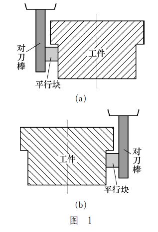
(1) Straight shank round bar pairing knife. This method is to clamp the straight shank round rod on the spindle.
Suppose the X-axis is divided: the moving spindle is slowly approaching one side of the workpiece. When approaching, use the parallel block to insert the gap between the round bar and the machined surface of the workpiece. When it feels easy to advance, take out the parallel block and continue. Move the spindle and re-plug the parallel block. If it is still easy to plug in or plug in, move the spindle again, and then reciprocate until it can just be inserted (see Figure 1), then zero the relative coordinate X axis; Then move the spindle to the other side of the workpiece. The same operation method is used to obtain the total value of the X-axis. After moving the spindle to half of the total value (middle of the workpiece), set the coordinate system. The advantage of this method is that the operation is simple and the required tools are not of high value; the disadvantages are that there are many operation steps, the process is cumbersome, and the precision of the tool is not high.
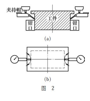
(2) Use a dial gauge to align the knife. This method is a flexible method of using several accessories of the lever dial gauge to achieve the method. The operation method is as follows: the clamping cap of the lever dial gauge is set on the main shaft, and then the dial gauge is attached to the clamping cap. Assuming the X-axis is divided, move the machine table to slowly press the dial gauge to the machined surface of the workpiece, manually rotate the spindle, and observe the maximum value of the dial indicator (if not an integer, move the spindle to adjust the dial gauge value) As an integer), as shown in Figure 2, then zero the relative axis of the X coordinate; then move the spindle to the other side of the workpiece, the same method of operation, the total value of the X axis, moving the spindle to half of the total value Set the coordinate system after (in the middle of the workpiece). The disadvantage of this method is that it takes a long time to machine the machine. When the processing depth of the front side is not enough, the edge of the blank easily interferes with the needle of the dial gauge or the dial indicator easily interferes with the vise jaw, and when the Y axis is divided, observe The dial gauge value is inconvenient; the advantage is that the tool is more accurate.
2. Improvement of the negative method
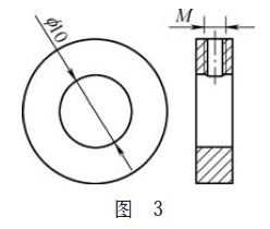
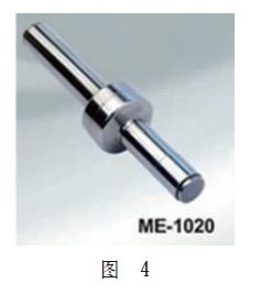
By summarizing the various sub-tools, it is found that the use of the eccentric edge finder is easy to operate, and the accuracy of the sub-center is high, but its characteristic is that the reverse side can not be completed. This is a major shortcoming of the eccentric edge finder. Therefore, after many experiments, the peripheral structure of the eccentric finder can be improved, and the original advantages can be retained, and the range can be extended to complete the reverse of the part. in. First, the outer and inner holes of the fitting shown in Fig. 3 are completed on a numerically controlled lathe, wherein the inner hole is just matched with the edge finder shown in Fig. 4, and the thickness is determined according to the processing condition of the part. Next, the threaded hole on the side is machined on the drill bed. The size of the threaded hole depends on the thickness. When the fitting shown in Fig. 3 is completed, it cooperates with the edge-finishing end of the edge finder, and then both of them are locked by the side screws.
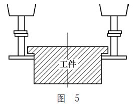
After completing the structural improvement of the eccentric finder, the next step is to complete the reverse of the part. After the clamping of the part is completed, the eccentric edge finder with improved structure is installed on the shank, and then the shank is mounted on the spindle. In the MDI mode, the input spindle is rotated forward, and the rotation speed is between 300 and 500 r/min. . Assume that the X-axis is completed: move the machine table under the handwheel mode, so that the improved eccentric finder is slowly approached to the machined surface on the left side of the workpiece. When approaching the workpiece, the handwheel accuracy can be adjusted to 0.01mm. Or 0.001mm, until just eccentric, as shown in Figure 5, in the relative coordinates, click the X axis to zero. Then exit, lift the spindle to the right side of the workpiece, the same operation method is close to the machined surface on the right side of the workpiece until it is just eccentric, watch the total value of the relative coordinates, calculate half of the value, and exit the eccentric edge finder. Lift the spindle to move to the center of the workpiece and set the workpiece coordinate system. Similarly, the Y-axis method is the same. The improved sub-central method not only ensures the processing accuracy, but also has the advantages of convenient observation and simple and quick operation.
3. Conclusion
The eccentric finder of the improved structure is easy to assemble and disassemble. When the side is required to be split, it can be easily removed by loosening the side screws; when the reverse side is required, it can be quickly installed. Depending on the condition of the part blank, several different sizes of accessories can be made for easy use. Of course, this method is mainly for small-scale processing enterprises or private workshops, and is most suitable for manufacturers who often produce some non-standard parts.


